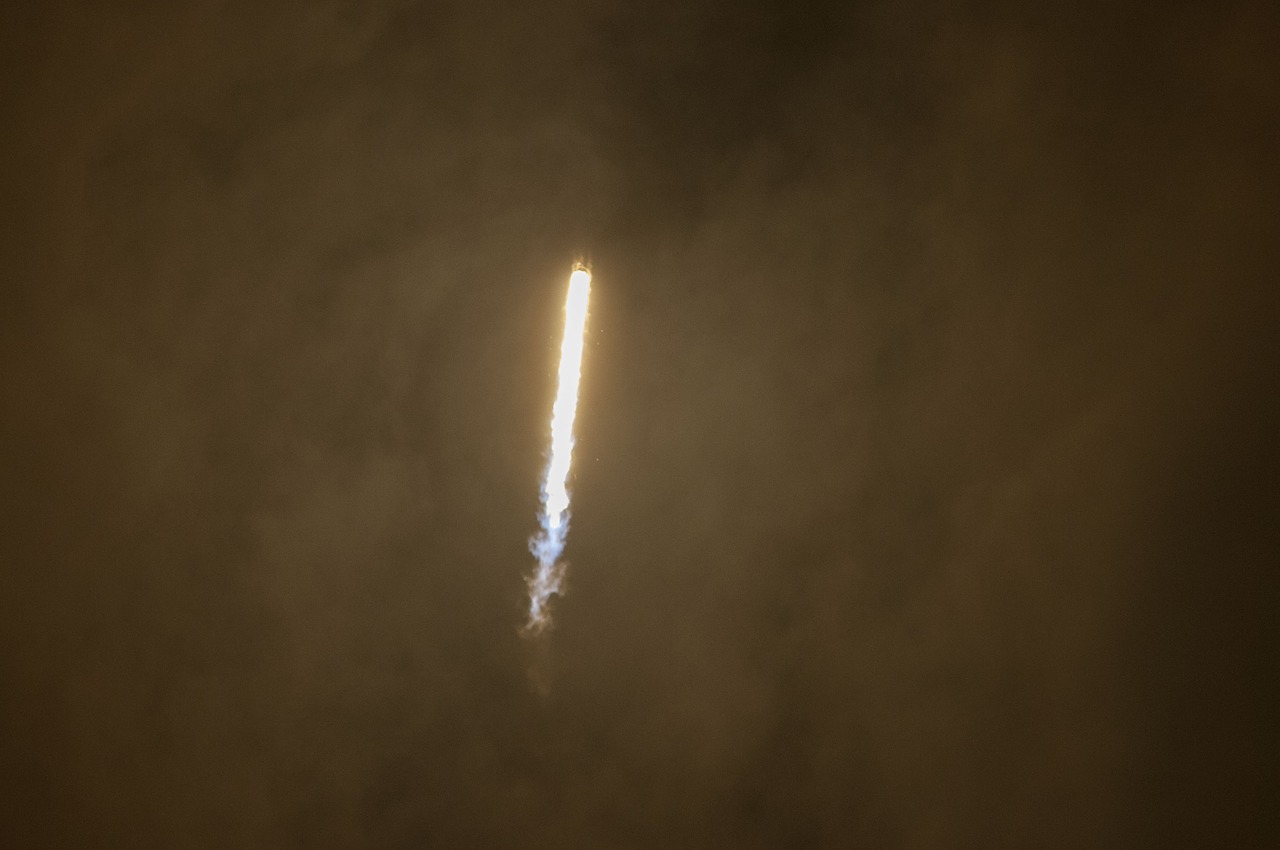
Turbojet engine is an air-breathing gas turbine engine that – much like rocket engines – produces forward thrust using the impulse generated by its exhaust gases.
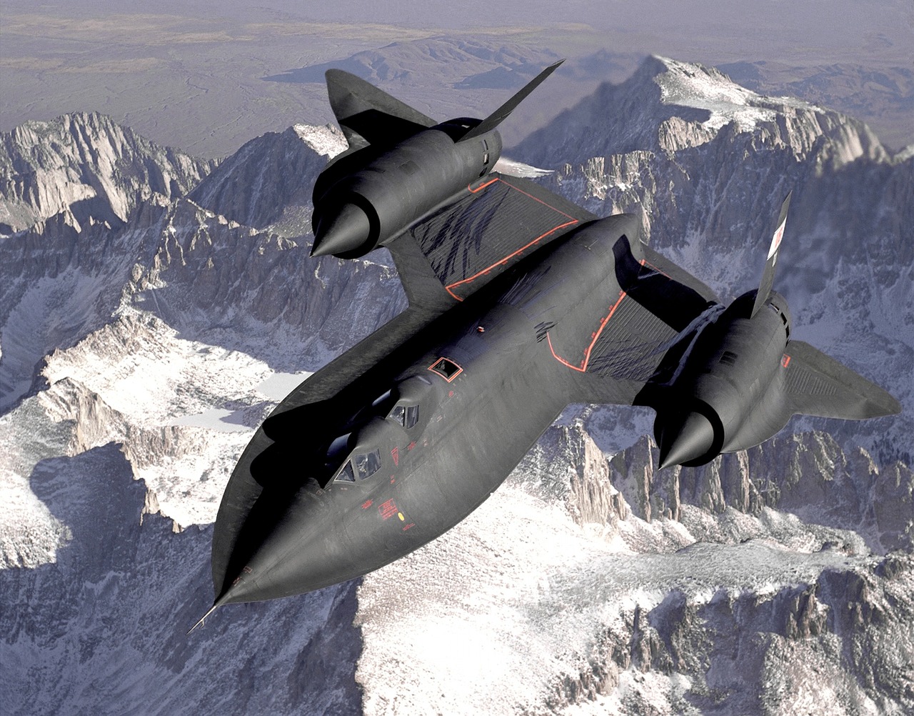
Turbojets are commonly used in military aircraft that require high velocities over short ranges.
Pratt & Whitney JT3D, J58 (Lockheed Martin Blackbird), F135 (Lockheed Martin F-35 and Raptor), General Electric CF700 (Cessna, Northrop), GTRE GTX-35VS Kaveri (HAL Tejas, Dassault Rafale), and several others are famous examples of some of the most powerful turbojet military fighter crafts in service, under development or decommissioned.
They were also used in commercial aircraft such as the British-French supersonic cruise passenger jet, Concorde.
Turbojet engines, however, are inefficient when used at low cruising velocities, and develop heating and fuel efficiency problems.
Regardless of its shortcomings, the turbojet engine has proven to be a thundering juggernaut in the battle skies.
Turbojet Engine Components Design
This engine comprises of four major parts – compressor, combustion chamber, turbine, and nozzle.
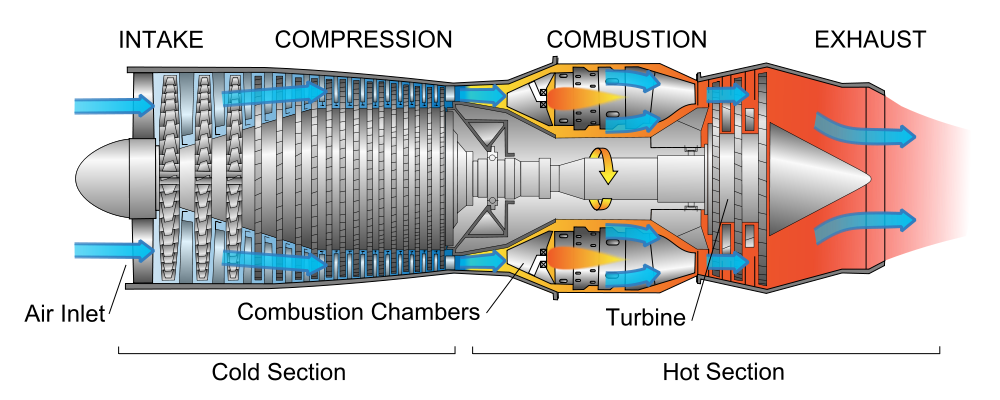
                                               Credits: Jeff Dahl
Modern turbojet engines have additional components such as afterburners and thrust vectors.
1. Air Intake
Before the compressor is the air intake or air tube, whose role is to bring the pressure ratios to engineered levels before feeding it to the compressor.
The inlet can have stationary vanes, movable vanes or no vanes that guide the stagnant air towards the compressor at a designed intake angle and pressure.
Air intakes are important as they contribute to the overall pressure ratio and thermal efficiency.
Turbojets require air intake pressure, temperature and velocity parameters to be at subsonic levels. And this is usually achieved with ease.
Supersonic turbojet engines, however, are engineered to handle supersonic air intakes and efficiently convert it into subsonic levels.
2. Compressor
The Auxiliary Power Unit (APU) – an electronic subsystem – initially rotates the turbine. The energy generated by the blades of this turbine powers the compressor through a system of wires and cables.
The compressor unit – which is tapered at the inlet and the outlet – siphons air from the intake. The air undergoes an adverse pressure gradient, sometimes in excess of 58:1 in many turbojet aircrafts.
But this gradient might result in separation of boundary layers on compressor blades, resulting in a stark reduction in performance.
In order to avoid this, compressors are usually multi-staged (also called spool) and compact.
A typical compressor comprises of a row of rotating blades called rotors and a row of stationary blades called stators. Each of these spools (which encompass the rows) can contain any where between 30 and 100 blades, which allows for engineers to obtain extremely overall high pressure ratios across the compressor unit.
Compressor rotors serve to accelerate incoming air and increase kinetic energy of the flow.
3. Combustion Chamber
The Combustion Chamber (CC) is a cylindrical unit with no taper, and is designed to burn the air-fuel mixture over a large volume while maintaining constant pressure. Minute pressure losses are common, however.
Fuel to the CC is supplied through injectors, which are small nozzles that spray atomized fuel on to the incoming air in a stoichiometric ratio.
A separate stream of air from the compressor is passed after the burning process, in order to the temperature of the products down to a level that the turbine blades can tolerate.
4. Turbine
The hot gases from the CC enter the turbine section and begin to expand. The turbine blades, like the compressor blades, are engineered at precise angles and lengths to accelerate the incoming fluid.
The turbine is split into several stages as per design requirements. The first stage of the unit (blades) increases the impulse of the flow to a large range. The later stages (nozzle like ducts) increase the kinetic energy of the flow.
The turbine additionally generates more power which is once again transferred to the compressor to keep the latter running.
Turbines are made of inconel and nimonic alloys to withstand the temperatures.
5. Nozzle
Although convergent nozzles are also in use, a typical turbojet nozzle is a de Laval nozzle, which is a convergent-divergent nozzle meant to accelerate the exhaust gases to supersonic range.
The nozzle has an intake convergent portion that pressurises the turbine gases to extremely large values. There is a circular portion called the throat of the nozzle, with almost zero length, which creates sufficient stagnation pressure and maintains the flow of the gases at sonic (speed of sound) levels. The velocity of the gases is now Mach 1.
A sudden, sharp change in divergent angle accelerates the fluid further to supersonic levels.
Supersonic velocities at the exhaust plume result in higher specific impulses and, thus, greater thrust values.
Brayton Cycle
Unlike typical combustion engines, the turbojet engine follows the Brayton Cycle, which is a thermodynamic cycle used for designing gas turbines.

                                                 Credits: Duk
The schema of the ideal Brayton process is as follows:
1. Isentropic compression of the ambient air by the compressor, where it is pressurised.
2. Isobaric heat addition in the CC, where the fuel is burned at constant pressure.
3. Isentropic expansion of the heated, pressurised gases in the turbine causes energy spike.
4. Isobaric process heat rejection to the atmosphere via the nozzle.
However, a real Brayton Cycle undergoes adiabatic compression, isobaric heat addition, adiabatic expansion and isobaric heat rejection due to energy losses and other contributing factors.
Problems Encountered by Aircraft Engineers
Brayton cycle, although powerful, has its own pitfalls that designers are constantly trying to out-engineer.
The Cycle, when not complemented with appropriate materials and cooling systems, increases the temperature of the gases from the turbine and in turn jet velocity beyond designed parameters, thereby reducing propulsive efficiency despite the high specific impulse.
Other problems include boundary layer separation at the intake and aerodynamic turbulence at high velocities.
After being incorporated with afterburners and thrust augmentation, turbojets are now being equipped with VTOLs, electrostatic shields, and many other technologies.
Turbojet engines are evolving constantly with the rise of ramjet and scramjet concepts that are already improving propulsive efficiency and minimising losses and dangers.
With these and many other upcoming concepts, turbojets might soon become the only type of turbine engines used in both military and commercial airspace.
0 Comments